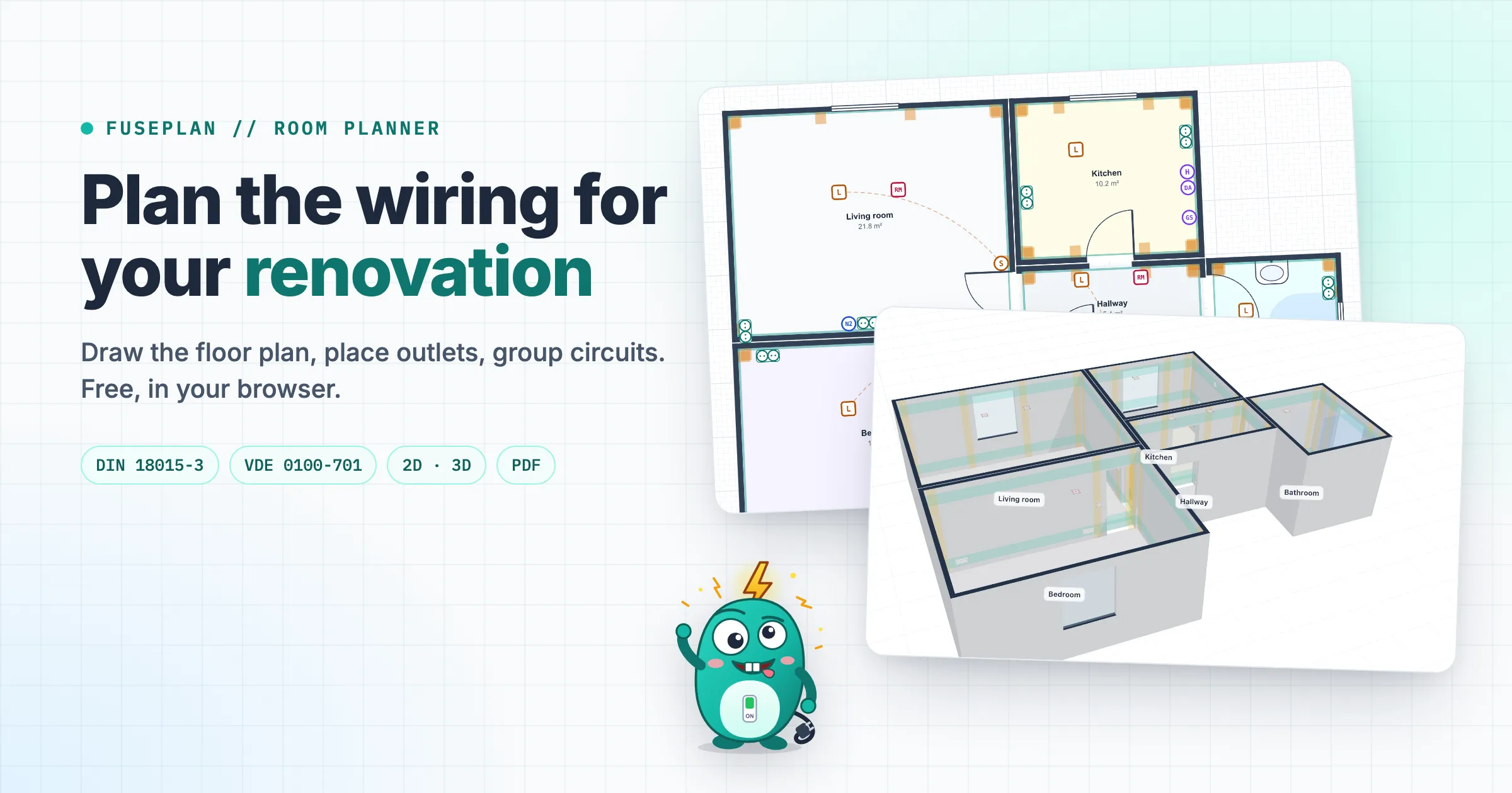
Plan the electrics for your renovation: free room planner
Plan an electrical renovation for free: draw your rooms, place outlets in the DIN 18015-3 zones, group circuits and hand your electrician a PDF.
When you renovate, electrical planning rarely starts at the fuse box. The first question is where the sockets, switches, lights and network outlets go in each room. Only then do you know how many circuits you need and how big the sub-distribution board has to be. Until now FusePlan only covered the second part. The new room planner covers the first: you draw your flat, place the outlets and get circuits, a populated board and a PDF for your electrician out of it. It runs in your browser for free and needs no account.
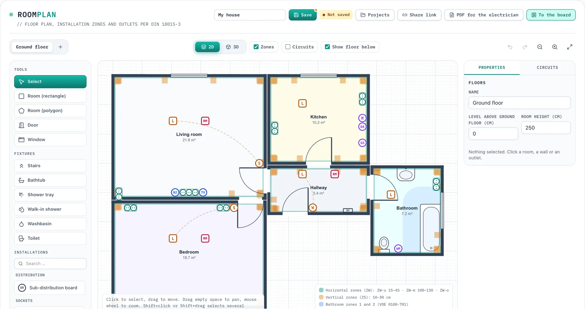
The example flat in the room planner. Teal marks the horizontal installation zones, amber the vertical ones beside corners, doors and windows.
Drawing the floor plan
You drag rooms out as rectangles or click them corner by corner as polygons. Corners snap to neighbouring rooms. Doors and windows go onto a wall with one click. For a house you add more floors and a staircase shows on its own floor and dashed on the floor above.
If you want to try it first, load the example flat: living room, bedroom, kitchen, hallway and bathroom, a little over 63 m² in total. All screenshots in this post show that flat.
The palette on the left holds the installations you usually plan from scratch in an electrical renovation. There are sockets from single to triple, sockets with USB, shaver sockets and IP44 outdoor sockets. Appliance outlets cover the cooker (400 V), oven, dishwasher, washing machine, dryer, cooker hood, instantaneous water heater and wallbox. For lighting there are ceiling and wall outlets, one-way, two-way and double switches, push buttons, dimmers and motion detectors. Network outlets, TV/SAT, telephone, Wi-Fi access points, smoke detectors, room thermostats and the doorbell are in there too.
Installation zones per DIN 18015-3
When you cut chases into the wall for new cables, the German standard DIN 18015-3 defines where those cables may run. Anyone who later screws a shelf to the wall then knows where cables can be. The room planner draws these zones on every wall:
| Zone | Position | Preferred line |
|---|---|---|
| ZW-u | 15 to 45 cm above the floor | 30 cm |
| ZW-o | 15 to 45 cm below the ceiling | 30 cm below the ceiling |
| ZW-m | 100 to 130 cm above the floor, only in rooms with work surfaces | 115 cm |
| ZS | 10 to 30 cm beside corners, doors and windows | 15 cm |
The middle zone ZW-m is on by default in kitchens and utility rooms. In any other room you switch it on with a tick box. When you place an outlet on a wall, it snaps to the preferred line of the nearest zone. If it ends up outside every zone, the planner marks it orange. The PDF puts a ”!” next to it, because the cable to that outlet has to come down as a vertical stub from a horizontal zone.
Doors and windows count for both rooms when the neighbouring room’s wall runs parallel within 60 cm. A door between hallway and kitchen therefore creates its vertical zones on both sides. Zones in the ceiling and floor are not part of the room planner.
Wall view: height and position of every outlet
Clicking a wall opens the wall view. It shows the wall head-on with all its zones and you drag outlets to the right height. Buttons set the common heights in one click: 30 cm for ZW-u, 105 cm for switches, 115 cm for ZW-m and the upper zone. Outlets keep 2 cm apart and stay out of door and window openings. Above a door or below a window sill is fine.
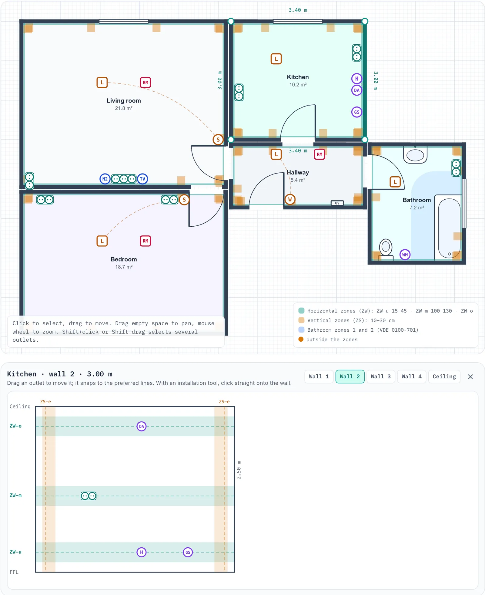
Kitchen wall 2: cooker hood at the top, worktop socket in ZW-m, cooker and dishwasher at the bottom.
Besides the walls, every room has a ceiling view. That’s where light outlets and smoke detectors go, with the distance to the nearest wall shown next to them.
Bathroom zones per DIN VDE 0100-701
The bathroom adds a second standard. Put a bathtub, shower tray or walk-in shower into the room and the planner draws the zones of DIN VDE 0100-701 (the German version of IEC 60364-7-701). Zone 1 sits above the tub or tray and reaches up to 225 cm. For a walk-in shower it covers 120 cm around the drain. Zone 2 extends 60 cm beyond zone 1, also up to 225 cm. A walk-in shower has no zone 2.
The planner flags sockets, switches and the board in both zones as not allowed. A shaver socket with an isolating transformer may sit in zone 2. Lights and fixed appliances get a note that they need at least IPX4. Washbasins and toilets have no zone of their own.
3D view
Click “3D” and the floor plan turns into a 3D view. The zones show as coloured bands on the walls and the outlets sit at their real height. With several floors you can show the lower floors as well.
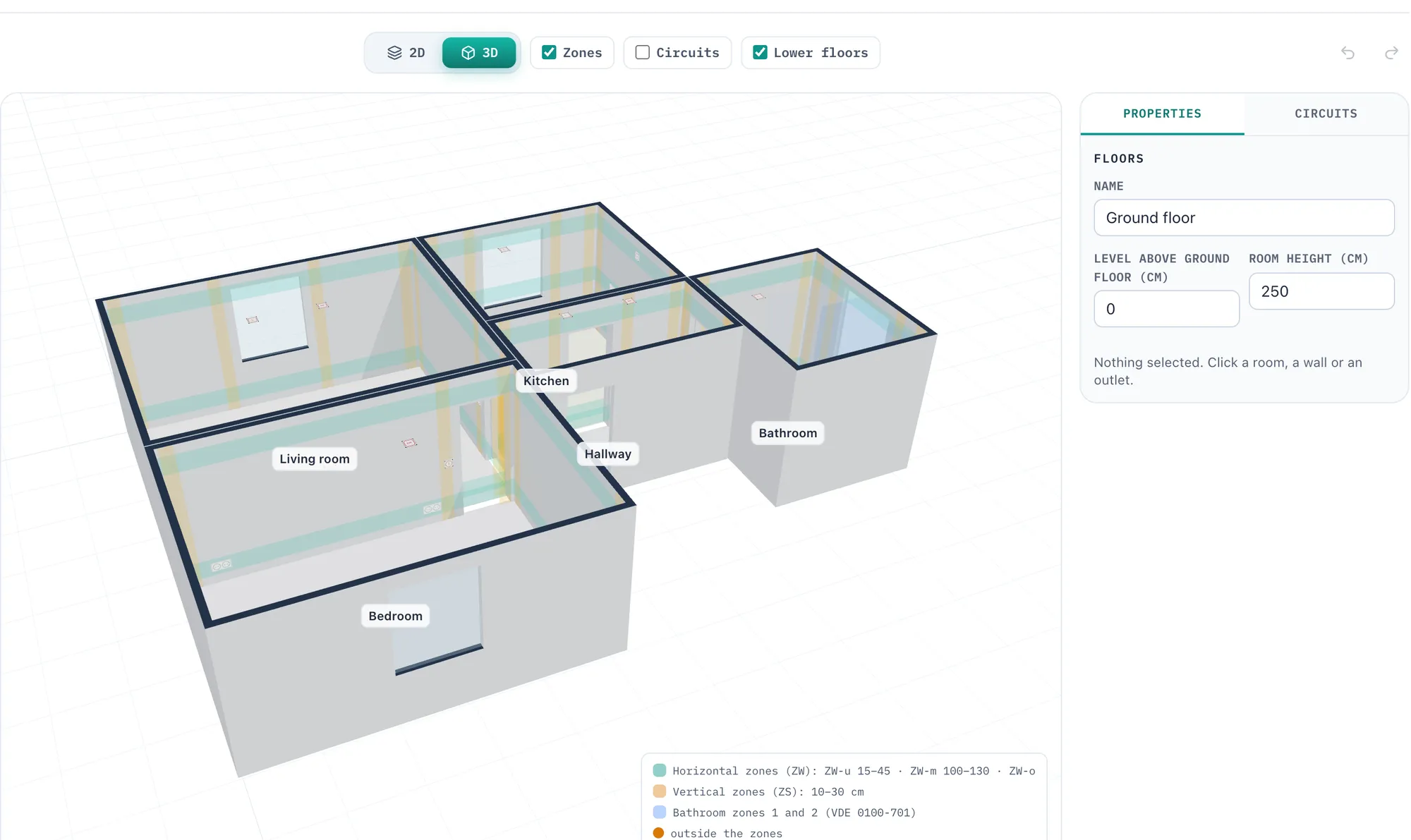
The same flat in 3D. The zones run as bands across every wall.
Switches, lights and circuits
A switch knows which lights it switches. If a room has only one switch or only one light without a switch, the planner links them on its own. The floor plan then shows a dashed line from switch to light. Other links you click together in the plan.
In the “Circuits” tab, “Suggest circuits” creates a first split: one circuit for the sockets of each room, one for the lighting of the floor and one for each large appliance. For the example flat that’s eight circuits. The lighting for the whole floor is on a B10, the cooker on a three-pole B16 and the dishwasher and washing machine get their own B16 each. The post on B, C and D characteristics explains the letters.
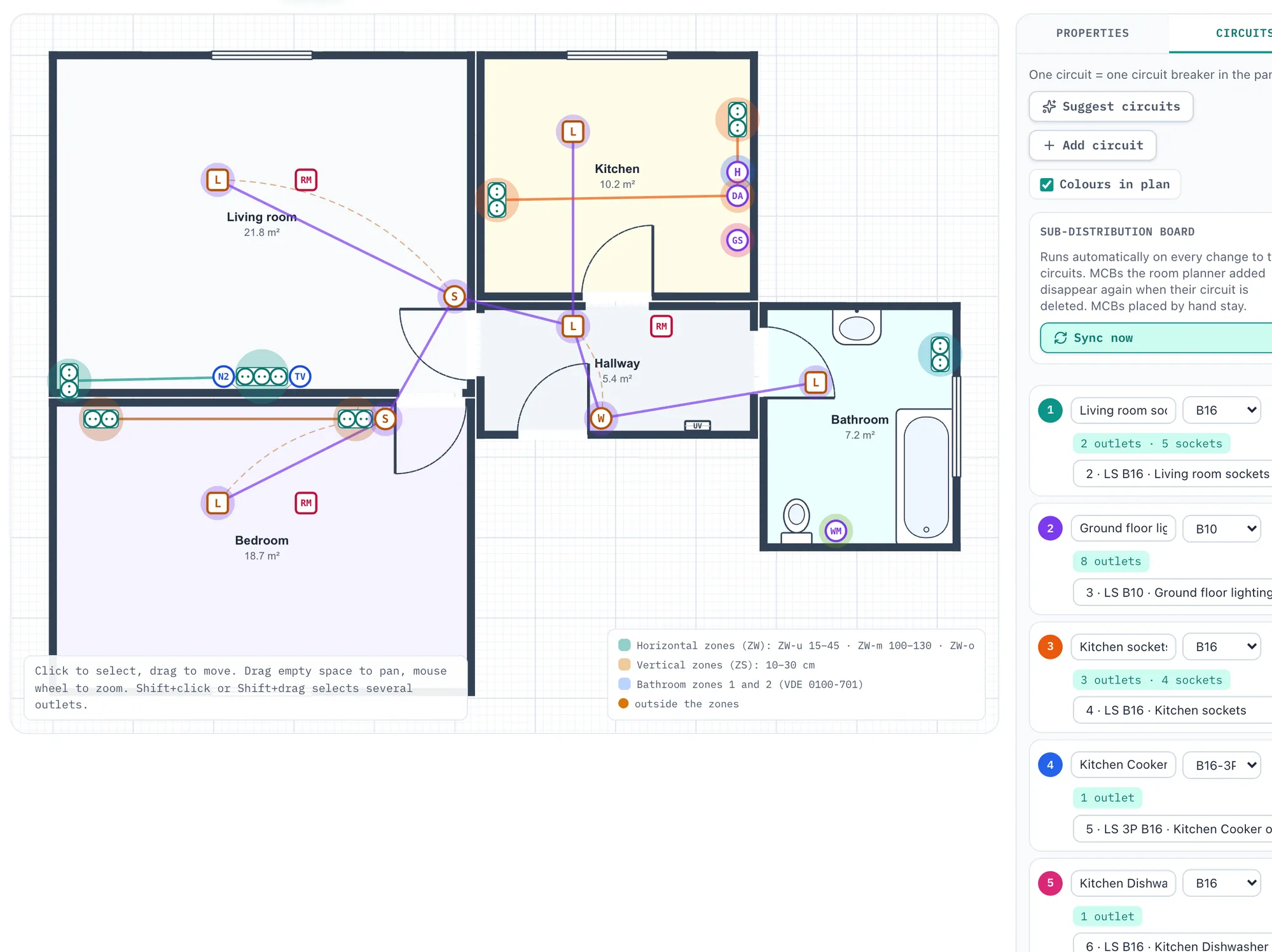
Every circuit has a colour. The list on the right shows which breaker in the board belongs to it.
“Colours in plan” colours every outlet by its circuit and joins the outlets of a circuit along the shortest connection. Those lines show what belongs together. They don’t plan the actual cable route. To assign several outlets to a circuit at once, select them with Shift+click or Shift+drag.
From circuits to the sub-distribution board
The room plan and the board are one project. About a second after every change to the circuits, the room planner updates the board. Every circuit with outlets gets a circuit breaker of its rating, labelled with the circuit’s name. New breakers go behind an RCD. Delete a circuit and its breaker disappears again. Devices you placed by hand in the board planner only get labelled. The sync never moves or removes them.
For the example flat that adds up to two four-pole type A RCDs (40 A, 30 mA), six B16 breakers, one B10 and one three-pole B16, 18 modules in total. The post on RCD type B+ explains why PV or a wallbox sometimes needs a different RCD type.
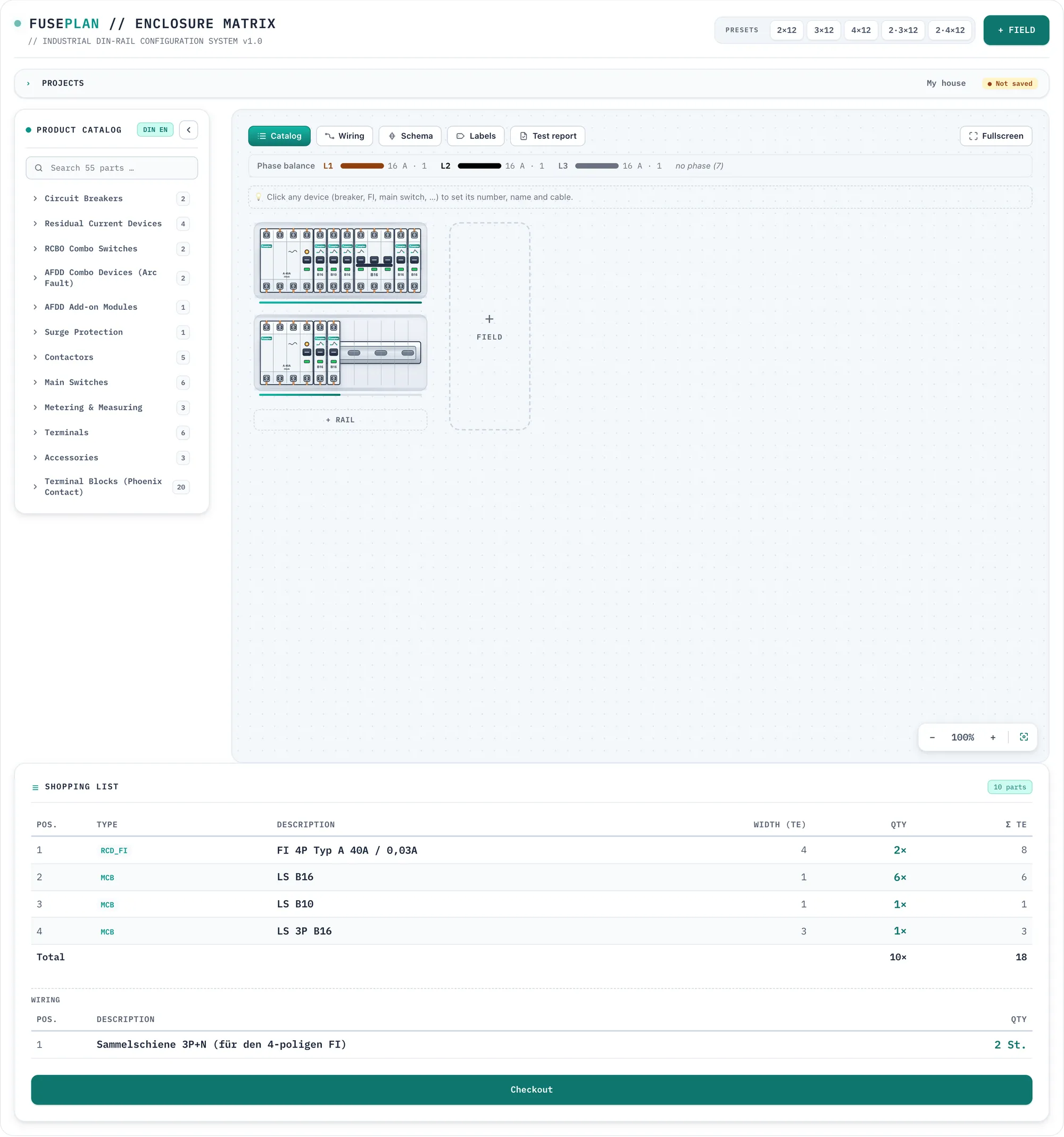
“To the board” opens the board planner. The breakers are already in place and so is the shopping list.
In the board planner you carry on with wiring, schematic, labels and test report. Why I built FusePlan describes how it works.
PDF for the electrician
“PDF for the electrician” creates a plan to print or email. It starts with an overview of quantities, the symbol legend and an explanation of the zones. The floor plan of each floor follows. Every room gets a table of all its outlets (wall, distance from the left, height, zone and circuit), with the wall views and their dimensions and the ceiling view below. At the end come the circuit list, a summary of the network outlets with the minimum number of patch panel ports and the quantities of all installations. For the example flat that’s ten pages.
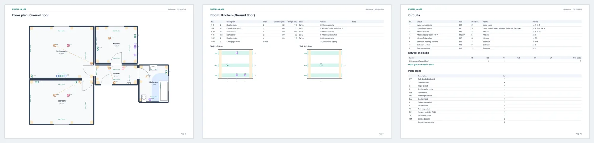
Pages 2, 5 and 10 of the PDF: floor plan, kitchen with wall views, circuits and quantities.
Saving and sharing
Every change goes straight into your browser’s storage, so reloading or switching to the board planner loses nothing. “Save” stores the project under its name. You can export it as a JSON file and import it again. “Share link” puts the whole project into a link that you can send to your electrician, for example. Nothing gets uploaded.
What the room planner doesn’t do
The room planner doesn’t size cables, doesn’t plan cable routes and doesn’t check whether the number of sockets per room meets a particular equipment level. It helps you get your plans down on paper, complete and with dimensions, before you talk to an electrician. Design, installation and sign-off stay with a qualified electrician.
Frequently asked questions
What does planning with FusePlan cost?
Nothing. The room planner and the board planner are free and need no account.
Can I plan my electrical renovation myself with it?
You can decide where each outlet goes, which circuits there are and what the board looks like. The PDF is a starting point for the conversation with your electrician, who checks the plan and does the installation and sign-off.
Which standards does the planner follow?
The installation zones of DIN 18015-3 and the bathroom zones of DIN VDE 0100-701. Both are German standards. Zones in the ceiling and floor are not included.
Does it work for a whole house?
Yes. You add more floors and connect them with stairs. The 3D view can show the lower floors as well.
The room planner is at fuseplan.app/editor/rooms/. “Load example flat” gives you a finished plan to try out in one click.
Comments
Write a comment